Multipath Fading Emulator
The Multipath Fading Emulator (MFE) is a Skytechnology software product developed to emulate the multipath fading effect typical of wireless communication channels using the “Two Paths” channel model.
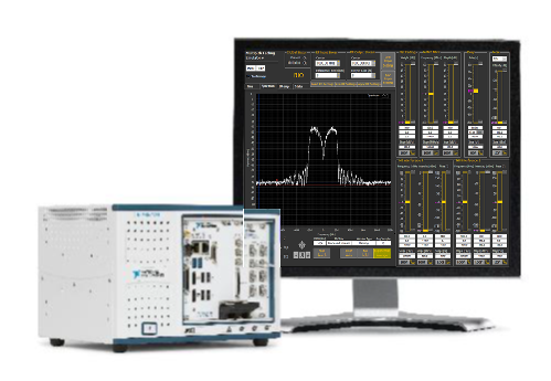
The MFE is targeted to work with National Instruments PXIe-5646R Vector Signal Transceiver that combines a vector signal analyzer and a vector signal generator with a user-defined FPGA for real-time signal processing and control.
The MFE consists of the FPGA programming file for the VST and a LabView user interface to control the instrument.
Main Features:
- Runs on NI PXIe-5646R VST – 200MHz instantaneous bandwidth

- Notch frequency run-time configurable over the whole bandwidth, slew rate up to 300MHz/s
- Notch depth run-time configurable up to 40dB over 98% of bandwidth, slew rate up to 300dB/s
- Fractional delay of second path run-time programmable sub-nanoseconds resolution.
- Additional impairments available – flat fading, noise, narrow band interference
- Center frequency and gain of RF In and RF Out streams independently configurable
- Possible to control remotely using SCPI commands over TCP/IP
The MFE implements the “Two-Rays” channel model using a custom FPGA configuration for the Vector Signal Transceiver. The user can simulate the effect of multipath propagation on the RF channel, both by controlling directly the frequency and the depth of the notch introduced by the channel model and by setting a different delay of the interfering ray with sub-nanoseconds resolution. It is possible to vary all impairments with a user defined slew rate and to make them automatically loop in a user-defined range of values with the set slew rate. Slew rates are hardware controlled (FPGA): parameters update period is less than 200μs.
Notch frequency can vary over the whole 200MHz bandwidth of the underlying hardware, 0.1 MHz resolution and slew rate up to 300MHz/s. Notch depth is up to 40 dB over 98% of bandwidth with resolution 0.1dB and slew rate up to 300dB/s. Interpath delay can range from -80ns to 80ns with resolution better than 0.5ns.
Architecture
The MFE architecture adheres to the underlying hardware: signal acquisition, processing and generation are carried in real-time on the user-defined FPGA, while system/test configuration and HMI are managed at the software level, on an integrated PXI controller.
HMI
The HMI let the user easily modify instrument parameters, all of them at run-time, thus allowing the operator to instantaneously see modifications.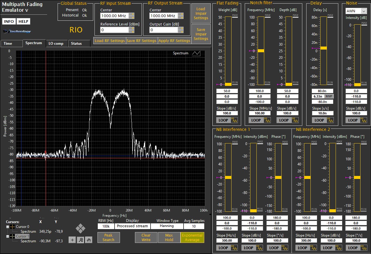
User interface is designed to be intuitive. Test parameters are logically grouped by functionalities and most of them can be modified run-time allowing the operator to instantaneously see the effect of the modifications. Tabbed graphs display the signal in time domain and its spectrum. Filtering options, cursors and display functions help the user achieving a better visualization of the signal spectrum. It is possible to control the MFE application remotely through SCPI commands over LAN.
Testing feature
MFE offers following testing features:
- Notch filter control: user may vary both notch frequency and depth at the same time;
- Notch sweep: this feature allows the conduction of automatic sweep of notch frequency over a definable frequency range.
- Propagation delay: whilst it is customary to conduct signature test at 6.3 ns, the software lets the user move the delay as needed, with a resolution better than 0.5 ns.
- Noise insertion: the instrument lets the user to add noise to the output signal, either uniform or Gaussian.
- Flat fading: the software allows the user to process the input stream by super-imposing a flat-fading effect.
- Continuous wave interference insertion: the user may add up to two narrow-band interferences, controlling CW frequency and attenuation independently for each of them.
- Input/output stream display: the software lets the user to select in real-time whether to display the input signal or the processed one. In this way user can investigate both input/output signals without additional external instrumentation.
- Local oscillator compensation: the software offers the possibility to set adjust factors to compensate for unwanted LO spurs contribution. Compensation has to be carried out measuring the output signal with a spectrum analyzer. The software offers the possibility to input adjust factors to compensate for unwanted LO spurious contribution.
- Different Frequency in/out: the instrument may use different clock rates for input and output streams.
- Slew rate:all the following parameters vary with a definable slew-rate:
- Notch frequency and depth
- Noise intensity
- Narrow Band frequency and intensity
- Flat Fading intensity
Slew rate control allows the operator to perform several tasks like avoiding the modem errors/communication interruptions or characterizing the DUT’s operational limits and determining devices operational ranges.
- Automatic execution of auto calibration: the application automatically manages hardware calibration in order to carry out correct measurements.
The supported version depending on the National Instruments’ VST is:

MFE flyer
MFE _200M (for NI PXIe-5646R)
To get more info about NI PXIe-5646 visit: